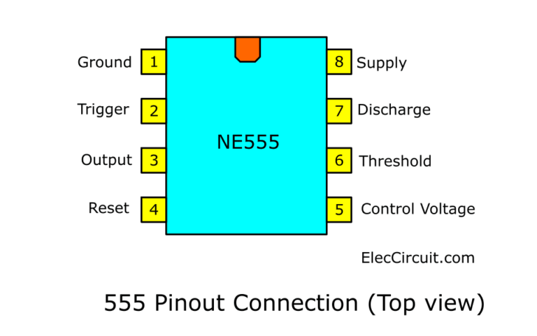

In most circuits, pin 7 is connected to the supply voltage through a resistor and to ground through a capacitor. This pin is used to discharge an external capacitor that works in conjunction with a resistor to control the timing interval. When this voltage reaches 2/3 of the supply voltage (Vcc), the timing cycle ends, and the output on pin 3 goes low. The purpose of this pin is to monitor the voltage across the capacitor that’s discharged by pin 7. This capacitor serves to level out any fluctuations in the power supply voltage that might affect the operation of the timer. Pin 5 is usually connected to the ground line through a small 0.01 ♟ capacitor. If it is momentarily grounded, the 555 timer’s operation will be interrupted and won’t start again until it’s triggered again via pin 2. This pin can be used to restart the 555 timer’s operation. This is an active low input, just like the trigger input. The output pin is where you would connect the load that you want the 555 timer to power. The 555 timer’s output is digital in nature. When the voltage of this pin drops to 1 / 3 Vcc (or the threshold voltage determined by the control terminal), the output terminal on Pin 3 will turn ON. Pin 1 connects the 555 timer chip to ground (0V). Uses include bounce-free latched switches.Īs a Schmitt trigger the the 555 operates as an inverter gate which converts a noisy input into a clean digital output. In bistable mode the 555 functions as a flip-flop circuit. In monostable mode the 555 functions as a “one-shot” pulse generator. In astable mode the 555 can operate as an electronic oscillator. 555 Timer IC is one of the commonly used IC among students and hobbyists. The 555 Timer got its name based on its internal design which uses three 5 kilo-ohm resistor in series in the internal design of the circuit, thus giving it the name 555 for the three 5 kilo-ohm resistor.


 0 kommentar(er)
